This guide describes a general workflow and does not claim hands-on testing. Machine, tap and material manufacturers remain the authority for speeds, feeds, lubricants and safety instructions.
Prepare the hole
Locate and support the work securely. Use a drill suited to the material and maintain alignment. Deburr the entry without creating an oversized chamfer that removes useful thread length.
- Wear required eye protection.
- Keep hands away from rotating tools.
- Stop the machine before clearing chips.
- Follow the machine and cutting-tool instructions.
Start and finish the thread
Start square to the hole. Use the chip-control method specified for the tap style and material; a universal fixed reversal pattern is not correct for every tap. Clean the hole before inspection.
Set up for alignment
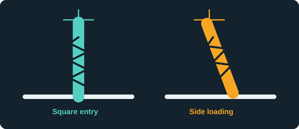
Hold the work securely and start the tap square to the drilled axis. A guided tap holder, tapping head or machine spindle is more repeatable than correcting a visibly leaning tap after it has begun cutting.
Check the drill and tap runout as assembled. A nominally correct drill can produce a poor pre-hole when the holder is dirty, the tool is bent or the setup lacks rigidity.
Plan depth and chip space
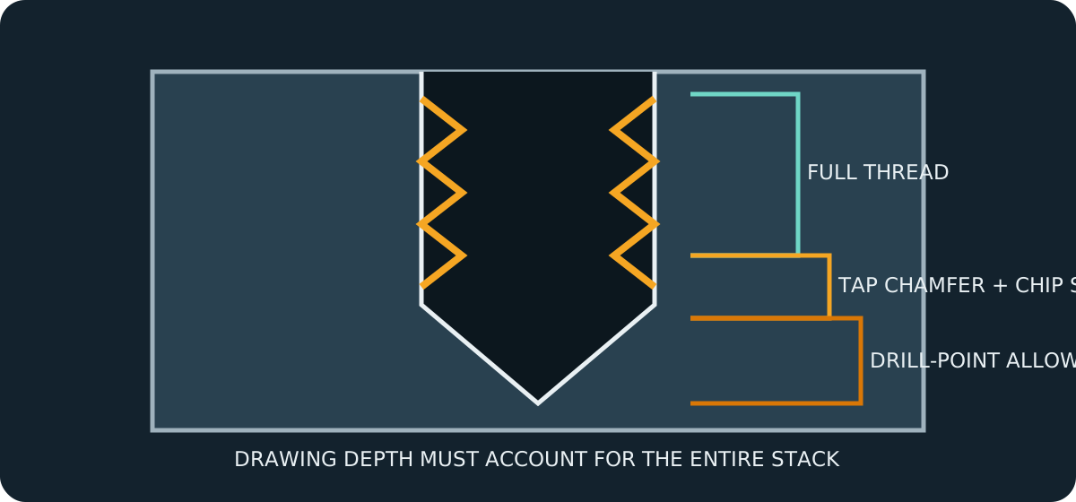
For a blind hole, total drill depth must exceed required full-thread depth. Allow for the drill point, the tap chamfer, a safe stopping margin and chip space; obtain exact allowances from the selected tools rather than a universal multiplier.
For a through hole, confirm that the tap and chips can exit without striking a fixture or hidden feature. Match chip direction to the hole: a spiral-point tool commonly drives chips forward, while a suitable spiral-flute tool can lift chips from a blind hole.
Inspect the first part
Clean the thread before gauging. Verify usable depth as well as fit, because an entrance can gauge correctly while the bottom portion is incomplete or packed with chips.
On repeat work, record actual pre-hole size, tool identification, lubricant, torque behavior and gauge result. A stable process is more valuable than one successful hand-tapped hole.
Broken taps and sharp chips can cause injury and scrap the part. Stop if torque rises unexpectedly or alignment is lost.
Technical references
- Tap Drill Sizes and Technical Formulas — Guhring, Inc.. Accessed 2026-11-10.
Standards references identify scope and terminology; protected dimensional tables are not reproduced.